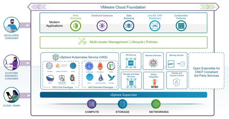
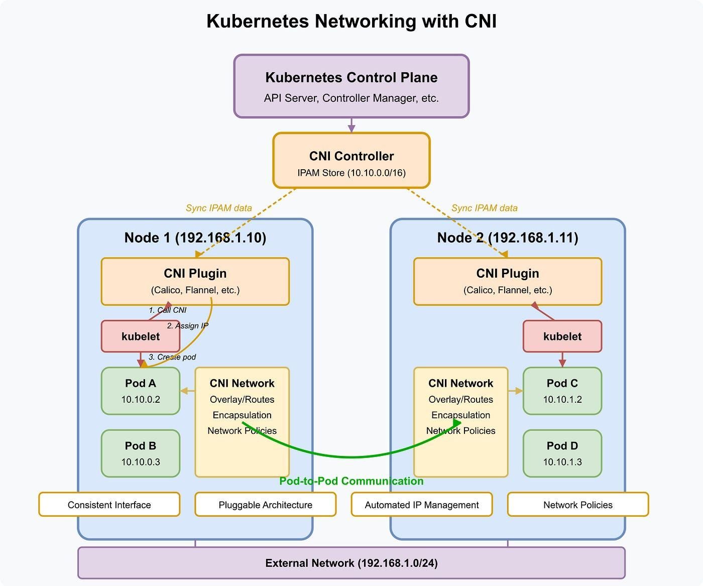
Kubernetes networking can look deceptively simple from the application developer’s perspective. A pod receives an IP address, a Service provides a stable endpoint, and an application connects to another workload using a DNS name.
Behind those familiar abstractions, however, packets travel through multiple networking layers. The Kubernetes Container Network Interface (CNI), virtual machine interfaces, vSphere networking, NSX constructs, physical switches, routers, and firewalls may all participate in the same communication path.
In VMware Cloud Foundation (VCF) 9.1 environments running VMware vSphere Kubernetes Service (VKS), understanding these layers helps platform engineers design connectivity, enforce security, troubleshoot application failures, and determine where Kubernetes networking ends and infrastructure networking begins.
This article follows the packet rather than treating networking as a collection of disconnected Kubernetes objects. We will examine how traffic moves between pods, Services, virtual machines, and external networks; compare Antrea, Calico, and bring-your-own-CNI approaches; and explore multi-network requirements for AI/ML, storage, telecommunications, and backend workloads.
The goal is to build a practical troubleshooting model that connects Kubernetes abstractions to the underlying vSphere and NSX infrastructure.
What You Will Learn
- How packets move between pods, Services, virtual machines, and external endpoints.
- How physical networking, ESX networking, VKS node networking, and pod networking fit together.
- The difference between node IPs, pod IPs, Service IPs, load-balancer IPs, and ingress or gateway IPs.
- How Antrea, Calico, and BYO CNI approaches differ conceptually.
- How Kubernetes networking relates to NSX segments, load balancing, network policies, gateways, and VPCs.
- How to troubleshoot connectivity systematically, from the pod to the physical network.
Table of Contents
- Start With the Packet
- Four Networking Layers
- Address Types
- Antrea
- Calico
- Bring Your Own CNI
- Multi-Network Support
- NSX and Kubernetes Constructs
- Troubleshooting Path
- Hands-On Lab
- Key Takeaways
- What I Learned
- Continue the Series
1. Start With the Packet
The most useful way to understand Kubernetes networking is to follow a packet from its source to its destination.
A successful application connection may involve DNS resolution, Kubernetes Service discovery, endpoint selection, pod routing, CNI forwarding, virtual switching, and possibly load balancing or firewall processing. Not every connection uses every component. The actual path depends on the source and destination, the CNI implementation, the Service type, routing configuration, and the underlying VKS deployment.
Pod-to-Pod Traffic

Pod-to-pod communication is the foundation of many distributed applications. An API pod may communicate with a database pod, a frontend pod may call a backend pod, or multiple workers may exchange data during a processing job.
The first question is whether the pods reside on the same Kubernetes node or on different nodes.
When both pods run on the same node:
- The source application sends a packet to the destination pod IP.
- The container networking stack processes the packet.
- The CNI implementation determines how the destination is reached.
- The packet may traverse local virtual interfaces, routing rules, or virtual switching components.
- The packet reaches the destination pod.
When the pods run on different nodes:
- The source pod generates a packet addressed to the destination pod IP.
- The source node’s networking configuration determines the appropriate route.
- Depending on the CNI architecture, the packet may be encapsulated in an overlay tunnel or forwarded using routed networking.
- The packet crosses the underlying node network.
- The destination node decapsulates or routes the packet as required.
- The packet reaches the destination pod.
The key distinction is that overlay and routed networking do not forward packets in exactly the same way. Overlay implementations add an encapsulation layer between nodes, while routed designs depend on routes that make the destination pod network reachable.
Do not assume that every VKS cluster uses the same packet path. Confirm the deployed CNI, node topology, and networking configuration before troubleshooting.
Pod-to-Service Traffic
Kubernetes Services provide stable virtual endpoints for applications whose individual pods may be replaced, rescheduled, or scaled.
For example, an application can connect to a Service named orders-api rather than tracking the IP address of each backend pod.
A typical request follows this sequence:
- The client resolves the Service name through cluster DNS, where applicable.
- The client sends a packet to the Service’s ClusterIP and port.
- The cluster networking implementation processes the Service destination.
- The request is directed to an eligible backend endpoint.
- The destination pod receives the request and returns a response.
The Service IP is generally a virtual address rather than an IP assigned to a conventional network interface. Depending on the implementation, Service forwarding may use iptables, IPVS, eBPF, or another supported mechanism.
This distinction matters when troubleshooting. A Service can exist and resolve correctly while its backend pods remain unreachable.
Useful checks include:
kubectl get svc -A
kubectl get endpoints -A
kubectl get endpointslices -A
kubectl get pods -A -o wide
Look for the following:
- Does the Service have the expected port and selector?
- Are the intended pods selected by the Service?
- Are endpoint addresses populated?
- Are the backend pods ready?
- Can the client reach the destination pod directly, where policy and routing permit?
If direct pod connectivity works but Service connectivity fails, investigate Service configuration and the CNI’s Service-forwarding implementation.
Pod-to-VM Traffic
Kubernetes applications often need to communicate with workloads that are not running inside Kubernetes.
Examples include:
- A VKS application connecting to a database hosted on a conventional virtual machine.
- A pod calling a legacy application deployed on vSphere.
- A monitoring agent collecting metrics from infrastructure services.
- A Kubernetes workload communicating with an internal API hosted outside the cluster.
The destination VM may have an address on a routable infrastructure network, while the source pod uses a cluster-specific pod address.
The packet path may include:
- The source pod networking stack.
- The node’s routing or CNI forwarding logic.
- The node’s virtual network interface.
- The vSphere virtual switch or NSX networking constructs.
- The infrastructure routing and security layers.
- The destination VM’s virtual network interface.
The reverse path is equally important. A VM may receive a request but fail to return traffic if the infrastructure lacks a route to the source pod network or if a firewall blocks the response.
When investigating pod-to-VM failures, validate both directions. Confirm that the VM’s IP is correct, that the intended TCP or UDP port is listening, and that routes and security rules permit the required traffic.
Pod-to-External Traffic
External connectivity includes access to public APIs, software repositories, container registries, package mirrors, and other services outside the private environment.
A common outbound path looks like this:
Application Pod → CNI → VKS Node → vSphere/NSX Networking → Router or Firewall → External Destination
Depending on the architecture, source network address translation (SNAT), a gateway, a proxy, or another egress mechanism may be involved.
For example, a pod might successfully resolve an external hostname but fail to establish an HTTPS connection. That symptom can indicate a routing, firewall, egress-policy, NAT, or remote-service problem rather than a DNS problem.
Test each function independently:
kubectl get pods -A -o wide
kubectl get networkpolicy -A
kubectl get nodes -o wide
Run connectivity tests from an approved diagnostic pod or workload using tools available in that image. Avoid assuming that curl, ping, nslookup, or packet-capture utilities are installed in every application container.
Packet-level lesson: identify the source address, destination address, protocol, port, and expected route before changing networking configuration. A precise packet path is much more useful than the general statement that “the network is down.”
2. Four Networking Layers
VKS networking is easier to understand when separated into four logical layers. These layers interact, but they are not interchangeable.

Layer 1: Physical Network
The physical network includes the Ethernet switches, routers, firewalls, physical NICs, VLANs, and upstream network services that connect the virtualization infrastructure to the rest of the environment.
Its responsibilities may include:
- Providing physical connectivity to ESX hosts.
- Carrying configured VLAN traffic.
- Providing routed reachability between infrastructure networks.
- Enforcing upstream firewall and segmentation rules.
- Supporting required MTU and jumbo-frame settings.
- Delivering external and inter-site connectivity where configured.
If an overlay network uses encapsulation, the physical network must be able to transport the resulting packets between the appropriate endpoints. MTU mismatches may cause fragmentation, packet loss, or failures that affect larger packets more noticeably than small connectivity probes.
Typical checks include switch-port configuration, VLAN availability, physical NIC link state, MTU consistency, and upstream routing.
The exact commands depend on the switch vendor, firewall platform, and network operating system.
Layer 2: ESX and vSphere Networking
The virtualization layer connects VM virtual NICs to the configured virtual networking infrastructure.
Depending on the deployment, this may include:
- vSphere Standard Switches.
- vSphere Distributed Switches (vDS).
- Port groups and VLAN-backed networks.
- NSX-backed segments.
- ESX physical uplinks.
- Virtual NIC configuration and connectivity.
A VKS worker node runs as a virtual machine. Its virtual NIC must be connected to the expected network, and the relevant virtual switching and uplink configuration must support the traffic.
If a worker VM has no connectivity to its expected node network, Kubernetes-level configuration alone will not resolve the underlying issue.
Useful inspection points include the worker VM’s virtual NIC, the selected network or port group, the host’s switch configuration, uplink health, and the intended VLAN or NSX segment.
Layer 3: VKS Node Network
The node network provides IP connectivity to the Kubernetes control-plane and worker-node VMs.
Node networking supports functions such as:
- Communication between cluster nodes.
- Access to the Kubernetes API endpoint.
- Required cluster-management communication.
- Access to DNS, NTP, registries, and other infrastructure services.
- Underlay connectivity for the selected pod-network architecture.
A node IP is not the same thing as a pod IP. The node IP belongs to the node VM’s network interface, while pod IPs are allocated through the cluster’s pod-networking design.
Check node readiness and node addresses:
kubectl get nodes -o wide
kubectl describe node <node-name>
These commands show Kubernetes-level information. They do not, by themselves, prove that every underlying VM interface, physical uplink, or network path is functioning correctly.
Layer 4: Kubernetes Pod Network
The pod network provides connectivity to application pods and supports communication between workloads.
Its behavior is influenced by:
- The deployed CNI.
- Pod IP allocation.
- Local and remote pod routing.
- Overlay or routed forwarding.
- Network policies.
- Service forwarding.
- Any supported additional network attachments.
The CNI is responsible for integrating pod networking with the node environment. Its exact implementation determines how interfaces, routes, forwarding, and policies are configured.
A pod can be running while its networking is broken. Similarly, a pod may have an IP address but remain unable to communicate because of routing or policy restrictions.
Inspect the pod’s node placement and IP:
kubectl get pods -A -o wide
kubectl describe pod <pod-name> -n <namespace>
How the Four Layers Fit Together
| Layer | Main responsibility | Example failure |
|---|---|---|
| Physical network | Carries packets between infrastructure endpoints | VLAN or uplink problem |
| ESX/vSphere | Connects VM NICs to virtual networks | Incorrect port group or segment |
| VKS node network | Provides node and infrastructure reachability | Node route or gateway failure |
| Kubernetes pod network | Provides pod connectivity and policy enforcement | CNI, endpoint, or policy issue |
A packet may pass through several of these layers, but not every flow uses every component in the same order. The troubleshooting goal is to locate the first layer where the expected behavior breaks.
3. Address Types
One of the most common sources of Kubernetes networking confusion is treating every IP address as if it represents the same thing.
In reality, a VKS environment can involve several different address types. Each has a distinct purpose, scope, and routing behavior.
Node IP
A node IP is assigned to a Kubernetes node’s virtual machine network interface.
It is used for node-level connectivity, including communication with infrastructure services and other nodes as required by the deployment.
Inspect node IPs with:
kubectl get nodes -o wideExample output:
NAME             STATUS   ROLES    INTERNAL-IP
vks-worker-01    Ready    <none>   10.20.10.21
vks-worker-02    Ready    <none>   10.20.10.22
Illustrative output only. Names, roles, and addresses will vary by cluster.
The INTERNAL-IP field represents the address Kubernetes reports for that node. It should not automatically be interpreted as the pod-network gateway, the external application address, or the IP used for every form of cluster communication.
Pod IP
A pod IP is assigned to a pod through the cluster’s networking configuration.
For example, a pod may have an address such as 192.168.100.15. This address is illustrative and does not imply that a particular VKS cluster uses that subnet.
Inspect pod addresses with:
kubectl get pods -A -o widePod IPs may change when workloads are recreated or rescheduled. Applications should generally use Kubernetes Services or another appropriate discovery mechanism instead of hard-coding individual pod addresses.
The scope and routability of a pod IP depend on the cluster’s CNI and network design.
Service IP
A Service IP, commonly called a ClusterIP, is a virtual address associated with a Kubernetes Service.
Inspect Services with:
kubectl get services -AExample:
NAME          TYPE        CLUSTER-IP      PORT(S)
orders-api    ClusterIP   10.96.20.15     8080/TCP
A ClusterIP is normally intended for access within the cluster’s networking environment. It is not necessarily assigned to a VM interface or advertised to the physical network.
Service traffic is forwarded to eligible backend endpoints through the configured Kubernetes networking implementation.
Load-Balancer IP
A load-balancer IP provides an address through which clients can access a Service of type LoadBalancer, when that functionality is configured and supported.
Inspect the relevant Services with:
kubectl get services -AExample:
NAME          TYPE           CLUSTER-IP     EXTERNAL-IP    PORT(S)
frontend      LoadBalancer   10.96.20.30    10.20.30.50    443:31443/TCP
Here, 10.20.30.50 is an illustrative external address.
The address may be allocated from a configured pool and implemented by a supported load-balancing solution. Its existence in Kubernetes output does not alone prove that the address is reachable from a client network.
Validate address allocation, routing or advertisement, firewall rules, listener configuration, and backend health.
Ingress or Gateway IP
An ingress or gateway IP is associated with the component that accepts and routes application traffic according to configured rules.
The exact meaning depends on the implementation:
- An Ingress resource defines HTTP or HTTPS routing rules consumed by an Ingress controller.
- A Gateway API configuration defines routing through the relevant gateway implementation.
- The controller or gateway may be exposed through a load-balancer Service or another supported networking mechanism.
Inspect the resources available in your cluster:
kubectl get ingress -A
kubectl get gateway -A
kubectl get httproute -A
Some resource types may not be installed, enabled, or permitted in a given cluster. A missing Gateway API resource is not necessarily evidence of a network failure.
Address Types at a Glance
| Address | Represents | Typical purpose |
|---|---|---|
| Node IP | Node VM network interface | Node and infrastructure connectivity |
| Pod IP | Pod network endpoint | Workload-to-workload communication |
| Service IP | Kubernetes virtual Service endpoint | Stable access to backend workloads |
| Load-balancer IP | Exposed Service address | Access from permitted client networks |
| Ingress/gateway IP | Application entry point | HTTP, HTTPS, or other configured routing |
Important: an IP address existing in a Kubernetes object is only one part of connectivity. Address allocation, routing, forwarding, policy, listeners, and return traffic must all work for a connection to succeed.
4. Antrea

Antrea is a Kubernetes networking solution built around Open vSwitch (OVS) and designed to provide pod connectivity and network policy capabilities.
In a VKS environment, Antrea’s availability and role depend on the supported product release and the selected cluster networking configuration. Do not assume that every VKS deployment uses Antrea as its default CNI without checking the platform configuration and release documentation.
Default CNI Role
The CNI provides the interface between Kubernetes workloads and the underlying networking implementation.
When Antrea is deployed as the cluster’s CNI, it participates in setting up pod networking and implementing supported networking features. Its components coordinate the networking behavior needed for pods to communicate across the cluster.
From an operational perspective, the key questions are:
- Is Antrea the CNI configured for this cluster?
- Are its components running and healthy?
- Are pod interfaces and routes configured correctly?
- Are the required node-to-node network paths available?
- Are network policies permitting the expected traffic?
Check the workload and system namespaces:
kubectl get pods -A -o wide
kubectl get daemonsets -A
Use these commands to identify networking-related workloads. Actual component names and namespaces depend on the installed Antrea deployment.
Overlay Behavior
Overlay networking allows workloads to communicate across nodes without requiring the physical network to understand every individual pod subnet.
In an overlay design, the packet may be encapsulated before crossing the node network and decapsulated when it reaches the destination node.
This creates a logical pod network on top of the underlying network.
Conceptually:
Source Pod → Source Node → Overlay Encapsulation → Underlay Network → Destination Node → Destination Pod
The physical network must still provide connectivity between the overlay endpoints. Overlay networking does not eliminate the need for correct VLANs, uplinks, routing, firewall rules, or MTU configuration.
The actual encapsulation protocol and forwarding behavior must be confirmed for the deployed implementation.
Network Policy
Network policy controls which workloads can communicate, subject to the capabilities and policy semantics supported by the CNI.
A Kubernetes NetworkPolicy can express rules based on pod selectors, namespaces, IP blocks, and ports. Its practical effect depends on whether the installed networking implementation enforces those rules and supports the required features.
Inspect existing policies:
kubectl get networkpolicy -A
kubectl describe networkpolicy <policy-name> -n <namespace>
For example, a policy may allow traffic from frontend pods to backend pods on TCP port 8080 while restricting other connections.
When debugging policy problems, review both ingress and egress rules, namespace and pod labels, protocol and port definitions, and the default-deny behavior created by the policies that select a workload.
A policy should not be assumed to block or allow traffic simply because its YAML appears syntactically correct.
Service Connectivity
Antrea can participate in the networking mechanisms used for Kubernetes Service connectivity, depending on its deployed configuration.
When a Service is unreachable, separate the problem into two questions:
- Can the client reach the intended backend pod?
- Does access through the Service work?
If direct pod access works but the Service does not, investigate Service selectors, endpoint readiness, Service ports, and the configured Service-forwarding mechanism.
If neither direct pod access nor Service access works, broaden the investigation to CNI health, node connectivity, routes, and network policy.
Integration With vSphere
Antrea and vSphere operate at different logical levels.
Antrea handles Kubernetes networking functions within its supported architecture. vSphere provides the virtualized infrastructure on which VKS node VMs run, including virtual NICs, virtual switching, and connectivity to the physical network.
The relationship can be summarized as follows:
| Component | Responsibility |
|---|---|
| Kubernetes | Defines pods, Services, and supported network-policy objects |
| Antrea | Implements configured pod networking and supported policy functions |
| VKS node VM | Hosts the Kubernetes node and its networking components |
| vSphere networking | Connects node VM interfaces to the infrastructure network |
| Physical network | Provides the underlying transport and external connectivity |
A healthy CNI cannot compensate for a disconnected worker VM network interface. Likewise, a healthy vSphere network does not guarantee that Kubernetes Services or pod policies are configured correctly.
5. Calico

Calico is another Kubernetes networking solution. It supports network policy and offers networking architectures that can include routed pod networking, BGP-based route distribution, and overlay networking, depending on the selected configuration and platform support.
Calico should not be described as exclusively an overlay solution or exclusively a BGP solution. Its behavior depends on how it is deployed.
Architectural Differences
A useful comparison focuses on how each implementation establishes connectivity and enforces policy.
| Area | Antrea | Calico |
|---|---|---|
| Networking foundation | Uses Open vSwitch-based networking | Supports multiple networking modes and dataplane options |
| Pod connectivity | Depends on configured Antrea networking | Depends on selected Calico routing and dataplane configuration |
| Network policy | Supports Kubernetes network policy and additional supported features | Supports Kubernetes network policy and additional Calico policy features |
| Routing | Depends on the configured forwarding architecture | May use routed networking, BGP, overlay networking, or supported alternatives |
| Operations | Requires familiarity with Antrea components and troubleshooting | Requires familiarity with the deployed Calico components, routes, and policy model |
This is a conceptual comparison, not a claim that every listed capability is available in every VKS release.
The practical question is not simply which CNI has more features. It is whether the selected networking architecture is supported by the target VKS deployment and fits the operational requirements.
Why an Enterprise Might Choose Calico
An enterprise may evaluate Calico when its networking team needs particular routing behavior, established policy workflows, or alignment with an existing Kubernetes networking standard.
Potential considerations include:
- Consistency with networking practices already used across Kubernetes environments.
- Requirements for routed pod networking or route distribution.
- Policy-management requirements across namespaces and workloads.
- Integration with existing monitoring, automation, and troubleshooting processes.
- Operational experience within the network and platform engineering teams.
These are evaluation criteria rather than guarantees. The correct implementation depends on the organization’s design and the specific VKS support matrix.
Policy and Interoperability Considerations
Selecting Calico involves more than installing a CNI package.
Before deployment, verify:
- Whether the target VKS release supports the intended Calico deployment model.
- Whether the CNI can be installed and managed using the supported cluster lifecycle.
- Which network-policy APIs and policy features are supported.
- Whether routing, IP allocation, and address ranges conflict with existing infrastructure.
- Whether the design requires BGP peering, encapsulation, or specific network reachability.
- How monitoring, upgrades, rollback, and troubleshooting will be managed.
A particularly important distinction is between a Kubernetes networking implementation that is technically capable of a feature and a configuration that is supported within the specific VKS platform architecture.
Validate both before adopting the design.
6. Bring Your Own CNI
Bring Your Own CNI (BYO CNI) refers to a deployment model in which the platform administrator supplies or manages a networking implementation instead of relying exclusively on the platform-provided networking configuration.
The exact meaning varies between Kubernetes platforms. In a VKS deployment, BYO CNI must be evaluated against the capabilities and lifecycle requirements documented for the specific product release.
Why BYO CNI Matters for Multi-Cloud Operations
Large organizations may operate Kubernetes across private cloud, public cloud, edge environments, and dedicated infrastructure.
Different environments can otherwise introduce separate networking tools, policy models, operational processes, and troubleshooting methods.
A standardized CNI strategy can help teams establish consistent practices for:
- Workload addressing and connectivity.
- Network policy design.
- Monitoring and troubleshooting.
- Network configuration automation.
- Security reviews and change management.
- Operational training across platform teams.
However, standardizing on the same CNI does not automatically make networks interchangeable. Cloud-provider integrations, routing, address allocation, load balancing, security enforcement, and cluster lifecycle management may still differ significantly.
The objective is to standardize the operational model where practical while explicitly documenting environment-specific behavior.
Interoperability and Security Requirements
Before adopting a BYO CNI design, examine the complete networking dependency chain.
Compatibility
Confirm compatibility with the supported Kubernetes release, VKS architecture, node operating environment, and lifecycle-management mechanisms.
IP address management
Check pod and node CIDRs against existing infrastructure networks. Overlapping ranges can cause routing ambiguity, connectivity failures, and difficulties when connecting clusters.
Routing and encapsulation
Document the intended forwarding model, any required route advertisements, overlay requirements, and underlay reachability.
Security
Validate network-policy enforcement, required control-plane communication, management access, and the boundaries between application traffic and infrastructure traffic.
Lifecycle
Define who installs, configures, upgrades, monitors, and repairs the CNI. Determine how CNI changes are coordinated with cluster upgrades and how a failed deployment can be recovered.
Operational Ownership
BYO CNI introduces an important ownership question: who is responsible when networking fails?
A practical responsibility matrix might look like this:
| Responsibility | Example owner |
|---|---|
| Cluster lifecycle | Kubernetes or platform team |
| CNI configuration | Designated networking/platform team |
| Pod and Service troubleshooting | Kubernetes operations team |
| Node VM and vNIC connectivity | Virtualization team |
| Physical routing and firewall policy | Network/security team |
| Cross-layer incident coordination | Platform operations or incident lead |
The exact ownership model varies by organization. What matters is defining it before production deployment.
A BYO CNI implementation should include documented health checks, supported configuration procedures, version compatibility, upgrade planning, and recovery instructions.
Design principle: use BYO CNI only when its benefits and support boundaries are understood. A familiar CNI is not automatically a supported CNI for every platform.
7. Multi-Network Support
Some workloads need more than one network attachment or traffic path.
A typical application may use a primary network for ordinary pod communication while requiring a separate network for storage, high-throughput data transfer, specialized equipment, or backend services.
Multi-networking can address these requirements, but it introduces additional design and operational complexity.

AI/ML Workloads
AI and machine-learning platforms can generate substantial east-west traffic between workers, data services, and supporting infrastructure.
Depending on the workload, teams may evaluate separate network paths for:
- Application and control traffic.
- Data ingestion and storage access.
- Distributed training traffic.
- High-throughput backend communication.
Specialized accelerators and distributed training frameworks may have their own networking requirements. Multiple network interfaces alone do not guarantee higher throughput or lower latency. Those benefits depend on the end-to-end design, supported hardware, network paths, MTU, bandwidth, and application behavior.
Storage Paths
Storage traffic can have different performance and availability requirements from ordinary application traffic.
For example, a design may distinguish application-facing connectivity from supported storage access paths.
However, a Kubernetes pod cannot automatically use any storage network simply because that network exists in vSphere. The storage architecture, CSI driver, node configuration, permissions, and supported attachment mechanisms must align.
Keep the following separate during design:
- Storage connectivity used by the infrastructure or node.
- Storage exposed to Kubernetes through a supported CSI implementation.
- Additional network interfaces explicitly attached to application pods, where supported.
These are related but different concepts.
Telco and NFV Workloads
Telecommunications and Network Functions Virtualization (NFV) workloads may require separate management, control, signaling, and data-plane networks.
Their requirements can include predictable connectivity, strict traffic separation, specialized packet-processing capabilities, and integration with existing network functions.
The architecture must be validated against the application’s performance requirements and the specific networking features supported by the VKS deployment. A general-purpose pod network should not be assumed to satisfy every carrier-grade or network-function requirement.
Service Chaining
Service chaining directs traffic through one or more network services, such as inspection, firewalling, or other traffic-processing components.
A service-chain design must define:
- Which traffic enters the chain.
- The order in which services process it.
- How return traffic follows the correct path.
- How routing and policy interact.
- What happens if a service becomes unavailable.
- How the chain is monitored and troubleshot.
Service chaining is not automatically provided by a Kubernetes Service or by creating a second pod network. It requires a compatible networking architecture and explicitly configured forwarding behavior.
Backend and Data Networks
Some applications need dedicated connectivity to internal databases, analytics systems, data pipelines, or specialized infrastructure.
A separate backend network may help with traffic separation and access control. But a second network interface is only one part of the design.
The team must also define addressing, routes, DNS behavior, firewall rules, policy enforcement, and how the application selects the intended interface or destination.
Multi-Network Design Checklist
| Design question | Why it matters |
|---|---|
| Does the platform support multiple pod network attachments for this deployment? | Prevents relying on an unsupported architecture |
| How are additional interfaces allocated and attached? | Establishes the mechanism for providing connectivity |
| Are IP ranges unique and non-overlapping? | Prevents address conflicts |
| Which interfaces carry application, storage, and management traffic? | Clarifies traffic separation |
| How is policy enforced on each network? | Avoids assuming that all networks share the same security behavior |
| How are routes and return paths configured? | Prevents asymmetric or unreachable traffic |
| How are performance and failures monitored? | Supports production troubleshooting |
| Who owns upgrades and network changes? | Clarifies operational responsibility |
The central principle is to define each network’s purpose, security boundary, addressing model, and owner before attaching it to a workload.
8. NSX and Kubernetes Constructs
NSX and Kubernetes both provide networking abstractions, but they operate at different layers and solve different problems.
Kubernetes defines workload-oriented objects such as Pods, Services, NetworkPolicies, and Ingress resources. NSX provides infrastructure networking capabilities such as logical segments, routing, distributed security controls, gateways, and load-balancing integrations, depending on the deployed NSX architecture and licensed capabilities.
Understanding the boundary between them is essential when designing VKS connectivity.
NSX Segment vs. Pod Network
An NSX segment is a logical network construct in the infrastructure networking layer. A Kubernetes pod network is the networking environment used to connect pods.
They are not interchangeable.
An NSX segment might connect VKS node VMs to an infrastructure network. The pods running on those nodes may use a separate CNI-managed network with its own addressing and forwarding model.
Conceptually:
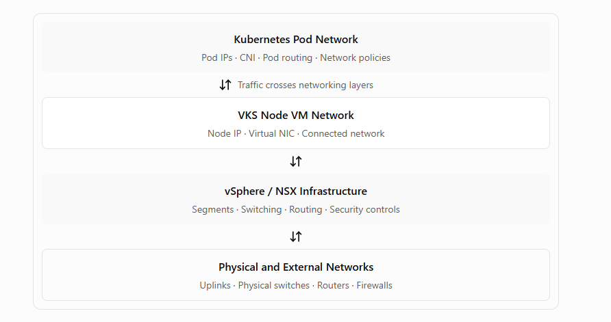
Conceptual model. The exact packet path depends on the selected VKS networking architecture and NSX configuration.
When a pod cannot reach an external destination, determine whether the traffic is expected to traverse the node network, an NSX-managed network, or another configured path. Do not assume every pod packet directly traverses an NSX segment.
Kubernetes Service vs. Load Balancer
A Kubernetes Service defines a stable way to access a group of application endpoints. A load balancer provides traffic distribution and an externally or internally reachable entry point when configured.
These functions can work together, but they are not the same resource.
For example, a ClusterIP Service provides an in-cluster virtual endpoint. A LoadBalancer Service requests a load-balancing implementation to expose the service according to the platform’s supported configuration.
Inspect the Kubernetes object:
kubectl get svc -A
kubectl describe svc <service-name> -n <namespace>
Then verify the infrastructure-side implementation, where applicable:
- Was an IP address allocated?
- Does the intended load-balancer listener exist?
- Is the address reachable from the client network?
- Are the backend endpoints healthy?
- Do routing and firewall rules permit the traffic?
The precise NSX objects and workflows involved depend on the deployed integration. Do not assume that creating a Kubernetes Service automatically creates a particular NSX object in every VKS architecture.
Network Policy
Kubernetes NetworkPolicy provides a workload-oriented way to express traffic restrictions. NSX security controls operate within the infrastructure networking layer and may enforce additional boundaries.
These mechanisms can complement each other, but their policies, selectors, enforcement points, and operational workflows are not identical.
For example, a Kubernetes policy might permit traffic from frontend pods to backend pods on TCP port 8080, while an infrastructure firewall restricts which external networks can reach the worker-node network.
When investigating a denied connection, determine:
- Which Kubernetes policies select the source and destination pods?
- Which CNI implementation enforces those policies?
- Are any additional infrastructure security rules applicable?
- Does the packet reach the node or infrastructure boundary?
- Is the return path permitted?
Avoid assuming that a policy in one layer replaces security controls in another.
Gateway and VPC Relationships
Gateways provide routing between networks or toward external destinations, depending on the architecture. VPCs provide logical networking constructs in supported NSX environments.
Their relationship with Kubernetes depends on how the VKS cluster and surrounding infrastructure are deployed.
A gateway may provide a route toward external networks, while a VPC or segment establishes logical network connectivity and isolation. Kubernetes Services and pod-networking components operate at their own abstraction levels.
Before using terms such as gateway, VPC, or segment interchangeably, document what each resource represents in the actual deployment.
A useful design diagram should identify:
- The node network and its gateway.
- The pod CIDR and the configured pod-routing model.
- The Service address range.
- Any allocated load-balancer address pools.
- The relevant NSX segments, VPCs, or gateways.
- The routes and security boundaries between them.
- The external networks that applications must reach.
This diagram becomes particularly valuable during incident response because it gives the platform, virtualization, and networking teams a shared view of the intended packet path.
9. Troubleshooting Path
When networking fails, troubleshooting is more effective when performed in a consistent order rather than changing multiple configurations at once.
The following path follows the layers specified in this article:
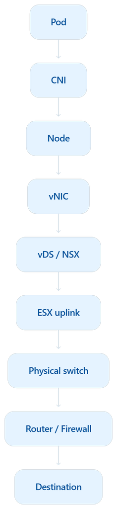
This is a diagnostic sequence, not a guarantee that every packet traverses every component in precisely this order. Local pod traffic, overlay traffic, routed pod networks, and Service traffic can follow different paths.
Step 1: Pod
Objective: establish whether the workload is running, has the expected IP, and is configured to communicate with the intended destination.
Commands:
kubectl get pods -A -o wide
kubectl describe pod <pod-name> -n <namespace>
kubectl logs <pod-name> -n <namespace>
Expected result:
- The pod is in the expected state.
- Its IP address is assigned.
- The pod is scheduled on the expected node.
- Application logs do not show an obvious startup or listener failure.
Failure symptoms:
Pendingor repeated restarts.- No assigned pod IP when one is expected.
- Application listening on the wrong port.
- Incorrect destination hostname or port.
- Application-level connection errors.
Next action: confirm the destination, protocol, port, and application listener before investigating the infrastructure.
Step 2: CNI
Objective: determine whether the pod-networking implementation is healthy and whether policies or forwarding rules explain the failure.
Start with:
kubectl get pods -A -o wide
kubectl get daemonsets -A
kubectl get networkpolicy -A
Inspect the networking components and logs using the actual component names and namespace in your deployment:
kubectl logs <cni-pod-name> -n <cni-namespace>
kubectl describe pod <cni-pod-name> -n <cni-namespace>
Expected result:
- Networking components are running as intended.
- Node-level networking agents are healthy where applicable.
- The expected network-policy objects exist.
- No relevant CNI errors are present in the inspected logs.
Failure symptoms:
- Networking agents repeatedly restart.
- Pod interface or route configuration errors.
- Missing or incorrect policy configuration.
- Service forwarding or cross-node communication failures.
- Errors associated with address allocation or networking initialization.
Next action: review the CNI-specific diagnostics and supported troubleshooting procedure. Do not apply generic Antrea commands to a Calico deployment, or vice versa.
Step 3: Node
Objective: establish whether the Kubernetes node is healthy and whether node-level connectivity is available.
Commands:
kubectl get nodes -o wide
kubectl describe node <node-name>
Expected result:
- The node is
Ready. - Its reported address is correct.
- There are no unexplained networking-related conditions or events.
Failure symptoms:
- Node is
NotReady. - Node networking or runtime errors appear in events.
- Node addresses differ from the expected design.
- Workloads on one node fail while equivalent workloads on another node work.
Next action: investigate the affected node’s network configuration, routes, DNS and infrastructure reachability as appropriate. Kubernetes commands alone may not expose the underlying VM networking problem.
Step 4: vNIC
Objective: verify that the node VM’s virtual network interface is connected and correctly configured.
Inspect the VKS node VM in the appropriate vSphere management interface.
Check:
- The virtual NIC is connected.
- The intended network or port group is selected.
- The expected IP configuration is present.
- Link and connectivity state are normal.
- The VM is attached to the correct network for the design.
Expected result: the node VM’s virtual NIC connects to the intended network and supports the expected node connectivity.
Failure symptoms:
- Disconnected virtual NIC.
- Incorrect port group or network assignment.
- Unexpected IP address or gateway.
- Connectivity failure isolated to one worker VM.
Next action: validate the virtual NIC and guest network configuration with the virtualization team. A VM network change should follow the supported platform procedure.
Step 5: vDS / NSX
Objective: verify the virtual switching and logical networking path used by the node VM.
Inspect the relevant vSphere Distributed Switch or NSX configuration, depending on the architecture.
Check:
- Port group or segment assignment.
- VLAN configuration where applicable.
- Logical connectivity and routing.
- Relevant distributed firewall or security rules.
- MTU and other required network parameters.
- Any applicable load-balancing or gateway configuration.
Expected result: the node VM is attached to the correct virtual network and the required forwarding and security behavior is configured.
Failure symptoms:
- Incorrect VLAN or segment assignment.
- Security rules denying the connection.
- Missing route or incorrect gateway.
- Unexpected behavior affecting VMs on a particular segment.
- Large packets failing because of MTU inconsistency.
Next action: identify the exact source and destination addresses and confirm where the traffic is expected to enter and leave the virtual network.
Step 6: ESX Uplink
Objective: determine whether the ESX host can carry the required traffic from its virtual switching layer toward the physical network.
Inspect the relevant host uplinks and switch configuration.
Where authorized and supported, an ESX shell check may include:
esxcli network nic listExpected result:
- The relevant physical NICs report the expected link state.
- The host has the expected uplink connectivity.
- The virtual switch is using the intended uplink configuration.
Failure symptoms:
- A physical NIC is down.
- Incorrect teaming or uplink configuration.
- VLAN traffic fails on a particular host.
- Connectivity problems correlate with workloads on a specific ESX host.
Next action: compare the affected host with a known-working host and validate the uplink configuration with the virtualization and network teams.
Step 7: Physical Switch
Objective: verify that the physical switch correctly receives and forwards traffic from the ESX uplink.
The exact commands depend on the switch vendor and operating system. There is no single universal command for this layer.
Inspect:
- Switch-port link state.
- VLAN membership and trunk configuration.
- Port-channel or link-aggregation status where applicable.
- MTU configuration.
- MAC learning and relevant interface counters.
- Errors, drops, or other signs of a faulty link.
Expected result: the physical switch port is operational and carries the required traffic for the intended VLANs and network paths.
Failure symptoms:
- VLAN missing from a trunk.
- Port or link aggregation down.
- Excessive drops or interface errors.
- MAC learning or forwarding behavior inconsistent with the design.
- Traffic failing only through a particular uplink or switch.
Next action: use the switch’s supported diagnostic commands to isolate the affected port, VLAN, or route.
Step 8: Router / Firewall
Objective: establish whether the destination network is reachable and whether routing and security policy allow the complete connection.
Inspect:
- Routes toward the destination.
- Return routes toward the source network.
- Applicable firewall rules.
- NAT or SNAT configuration where required.
- DNS resolution, if a hostname is involved.
- Destination listener and port availability.
- Load-balancer routing or health where applicable.
Expected result: the forward and return paths are valid, the required protocol and port are permitted, and the destination service is reachable.
Failure symptoms:
- Connection timeouts.
- Firewall denies or drops.
- Missing return routes.
- Incorrect NAT behavior.
- TCP connection refused because no service is listening.
- Successful DNS resolution but failed connectivity.
Next action: compare the source, destination, protocol, port, and timestamps against routing and firewall logs. Determine whether the packet reaches the destination and whether the response returns.
Troubleshooting Reference Table
| Layer | Commands or inspection | Expected result | Failure symptoms |
|---|---|---|---|
| Pod | kubectl get pods -A -o wide; kubectl describe pod | Correct pod state and IP | Pod startup, IP, or listener problem |
| CNI | kubectl get daemonsets -A; inspect CNI logs and policies | Networking components healthy | CNI errors, policy or forwarding issue |
| Node | kubectl get nodes -o wide; kubectl describe node | Node is Ready with expected address | Node connectivity or readiness failure |
| vNIC | Inspect VM in vSphere | Correct network attachment and connectivity | Disconnected NIC or wrong network |
| vDS / NSX | Inspect switch, segment, routes, security, and MTU | Expected virtual-network behavior | Incorrect assignment, routing, or security |
| ESX uplink | esxcli network nic list where appropriate | Relevant uplinks operational | Link, teaming, or host-specific issue |
| Physical switch | Vendor-specific interface and VLAN commands | Correct link and VLAN forwarding | Trunk, port, MTU, or forwarding issue |
| Router / Firewall | Route tables, firewall logs, listener checks | Valid forward and return paths | Denied traffic, missing route, timeout |
A Practical Isolation Strategy
Use these questions to narrow down the failure:
- Can the application resolve the destination? If not, inspect DNS and name configuration.
- Can the application reach the destination directly? Use an approved test and distinguish a TCP failure from a DNS failure.
- Does direct pod connectivity work while Service connectivity fails? Focus on Service configuration, endpoints, and forwarding.
- Does the failure affect only one node? Investigate node-specific CNI health, VM networking, and ESX placement.
- Does the failure affect traffic across nodes but not within one node? Inspect the inter-node path, routing, overlay transport, and MTU.
- Does the failure affect only external destinations? Examine egress configuration, gateways, routes, NAT, and firewalls.
- Does traffic reach the destination but not return? Investigate the reverse route and return-path security policy.
Change one variable at a time and preserve relevant logs and timestamps. This reduces the risk of masking the original failure with unrelated configuration changes.
10. Hands-On Lab
This lab focuses on observing the networking behavior of an existing VKS cluster. It does not assume that Antrea, Calico, NSX, multi-network attachments, or a particular load-balancer implementation are enabled in every environment.
Use an authorized lab cluster and replace the example names, addresses, and ports with values appropriate to your deployment.
Step 1: Inspect Nodes and Pods
Check the current Kubernetes context before running commands:
kubectl config current-context
kubectl get nodes -o wide
kubectl get pods -A -o wide
Record:
- Node names and addresses.
- Pod IPs and node placement.
- Pods that are not ready.
- Workloads that run on different nodes.
This establishes the baseline before testing connectivity.
Step 2: Identify the Networking Components
List system workloads and DaemonSets:
kubectl get daemonsets -A
kubectl get pods -A -o wide
Identify the CNI and its relevant components using the actual names in your environment.
Do not assume that a particular namespace or DaemonSet name is universal across VKS releases or custom deployments.
Record the CNI implementation and the configuration source used by the platform team.
Step 3: Inspect Services and Endpoints
Run:
kubectl get svc -A
kubectl get endpoints -A
kubectl get endpointslices -A
Choose an application Service and verify:
- Its type and ClusterIP.
- The Service port and target port.
- Its selected backend endpoints.
- The readiness of the backend pods.
If the Service has no eligible endpoints, inspect the selector, pod labels, and readiness before investigating the physical network.
Step 4: Test Pod-to-Pod Connectivity
Use two authorized test workloads, ideally placed on different nodes. Use a diagnostic image that contains the necessary networking tools.
First inspect placement:
kubectl get pods -n <namespace> -o wideThen perform a protocol-appropriate test from the source workload to the destination pod or its test listener.
For example, if the diagnostic image includes curl and the destination serves HTTP:
kubectl exec -n <namespace> <source-pod> -- \
  curl -v --connect-timeout 5 http://<destination-pod-ip>:8080/
The command assumes an HTTP listener on TCP port 8080; change it to match the test workload.
Expected result: the destination responds through the intended pod-network path.
If it fails: verify the listener, node placement, routing, CNI health, and applicable policy. A failed HTTP request alone does not prove that the underlying network is broken.
Step 5: Test Service Connectivity
From an authorized client pod, test the Service DNS name and port:
kubectl exec -n <namespace> <source-pod> -- \
  curl -v --connect-timeout 5 http://<service-name>.<namespace>.svc.cluster.local:8080/
This example assumes that the cluster uses the standard Service DNS naming pattern and that an HTTP endpoint is listening on the selected port.
Compare the result with the direct pod test.
- If direct pod access and Service access both work, the tested path is functioning.
- If direct pod access works but Service access fails, inspect Service ports, selectors, endpoints, and Service forwarding.
- If both fail, continue investigating the pod, CNI, node, and network path.
Step 6: Inspect Network Policies
List the policies in the test namespace:
kubectl get networkpolicy -n <namespace>
kubectl describe networkpolicy -n <namespace>
If policies are present, check whether the source and destination workloads are selected and whether the relevant protocol and port are permitted.
Use a controlled test to determine whether the observed result matches the intended policy. Do not remove production policies merely to test connectivity.
Step 7: Validate Infrastructure Connectivity
If the test indicates an infrastructure-layer problem, inspect the relevant VKS node VM in vSphere.
Record:
- Node VM name and ESX host.
- Virtual NIC and network assignment.
- Relevant vDS or NSX segment.
- Node IP, subnet, and gateway.
- Uplink status and physical network dependencies.
For external connectivity, work with the infrastructure team to validate the forward and return routes, applicable firewall rules, and destination listener.
Step 8: Document the Results
Use a test record like this:
| Test | Result | Evidence to capture |
|---|---|---|
| Node readiness | Pass / Fail | kubectl get nodes -o wide |
| CNI health | Pass / Fail | Relevant component status and logs |
| Pod-to-pod | Pass / Fail | Test output, source/destination, node placement |
| Pod-to-Service | Pass / Fail | Service definition and test output |
| Network policy | Pass / Fail / Not applicable | Policy definitions and controlled test |
| Node VM networking | Pass / Fail / Not checked | vNIC and network assignment |
| External connectivity | Pass / Fail / Not applicable | Route, firewall, and destination evidence |
Do not mark an untested layer as passed. Recording what was actually tested makes the lab useful for future troubleshooting and production readiness reviews.
Key Takeaways
- Kubernetes networking becomes easier to troubleshoot when you follow the packet from the source to the destination.
- Pod IPs, node IPs, Service IPs, load-balancer IPs, and ingress or gateway IPs serve different purposes.
- Physical networking, vSphere networking, node networking, and pod networking are separate layers with different failure modes.
- Antrea and Calico provide different networking architectures and operational considerations. Their supported capabilities must be verified against the target VKS release.
- BYO CNI requires explicit attention to platform compatibility, security, interoperability, and operational ownership.
- Multi-network requirements should be designed around specific workload needs, addressing, routing, security, and lifecycle management.
- NSX constructs and Kubernetes objects operate at different abstraction levels. Their integration depends on the actual deployment architecture.
- A repeatable troubleshooting path helps teams identify the failing layer without changing unrelated settings.
What I Learned
Use this section to summarize the practical findings from your own lab. For example, after performing the tests, you could document how the packet path differed between direct pod access and Service access, which networking components were involved, and which evidence helped narrow down a failure.
If you have not performed the lab, keep this section as a planned learning summary rather than claiming that specific tests succeeded.
Continue the Series
- Previous Article: VKS Architecture Deep Dive: How Kubernetes Actually Runs on VMware Cloud Foundation 9.1
- Previous Article: Deploying VKS on VCF 9.1: From Supervisor to Production Kubernetes Cluster
- Next Article: Article 4 — continue with the next topic in your planned VKS series.