Introduction
Deploying a Kubernetes cluster in an enterprise environment involves more than selecting a Kubernetes version and running a command. A successful deployment depends on the readiness of the underlying infrastructure, the configuration of the vSphere Supervisor, network connectivity, storage availability, identity and access controls, and the availability of supported Kubernetes releases.
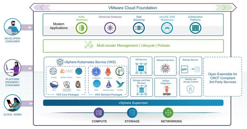
VMware vSphere Kubernetes Service (VKS) on VMware Cloud Foundation (VCF) 9.1 provides a platform-integrated approach to Kubernetes cluster provisioning and lifecycle management. Through declarative APIs and Cluster API-based workflows, authorized consumers can request clusters while the platform coordinates the resources required to bring them into operation.
However, declarative provisioning does not eliminate the need for careful architecture and preparation. An incorrectly planned network, insufficient compute capacity, unavailable storage policies, or an unsupported Kubernetes release can prevent deployment from completing successfully.
This article moves from the architecture concepts discussed in Article 1 to a practical implementation workflow. We will review the pre-deployment design decisions, prepare the vSphere environment, validate the Supervisor and namespace configuration, select the Kubernetes release, build a cluster specification, and verify the resulting cluster.
The objective is to explain both what to configure and why each decision matters.
Table of Contents
- Pre-Deployment Design Table
- Deployment Prerequisites
- Deployment Walkthrough
- Illustrative YAML
- Small vs. Large Cluster Models
- Hands-On Lab: Deploy a Three-Control-Plane, Three-Worker VKS Cluster
- Troubleshooting and Validation
- Key Takeaways
- What I Learned
- Continue the Series
- References and Further Reading
1. Pre-Deployment Design Table
Before deploying VKS, establish the target architecture and confirm that its requirements can be met by the existing VCF environment.
The following table preserves the design areas identified in the deployment plan.
| Area | Decision |
|---|---|
| Compute | ESXi cluster and available capacity |
| Supervisor | Single-zone or multi-zone deployment |
| Networking | NSX or vSphere Distributed Switch-based model |
| Storage | vSAN, NFS, FC, or another supported design |
| Kubernetes | Supported VKr version |
| Worker sizing | VM classes and node pools |
| Persistence | Storage policies |
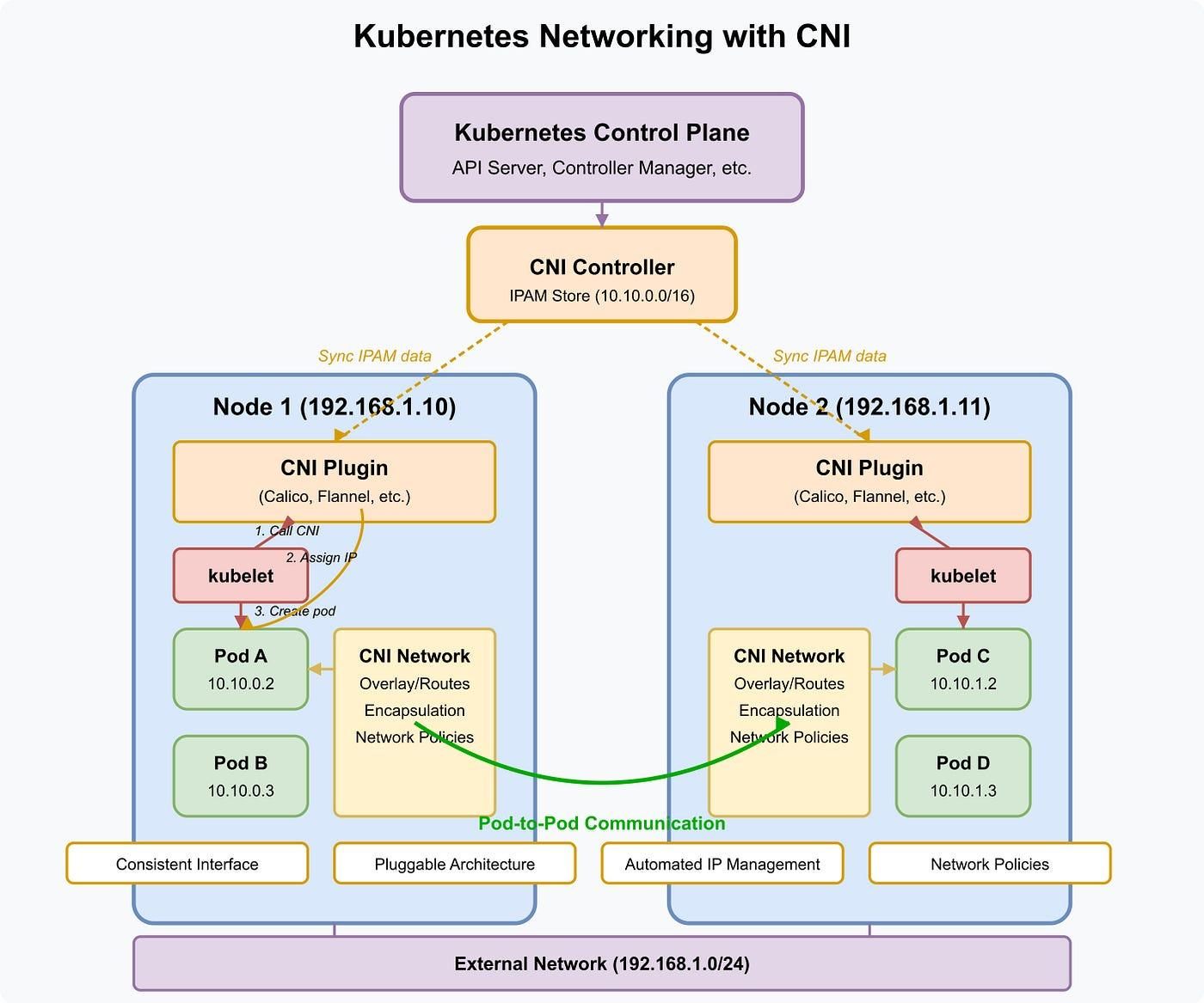
| CNI | Antrea, Calico, or BYO CNI where supported |
| Load balancing | Platform-supported implementation |
| Registry | Harbor or external registry strategy |
| Identity | Enterprise authentication and authorization |
| Availability | Control-plane and worker topology |
Each decision affects the deployment in a different way.
Compute: ESXi Cluster and Capacity
Determine which ESXi cluster or supported infrastructure pool will host the VKS node virtual machines.
Review the available CPU and memory capacity, existing workload utilization, reservations, and expected growth. Include the resource requirements of the control plane and all planned worker nodes, while retaining sufficient headroom for infrastructure operations and workload growth.
Also verify that the cluster has the required compatibility, connectivity, and resource-management configuration.
A cluster may have enough aggregate CPU and memory on paper but still experience scheduling problems if resources are constrained by placement, reservations, or other policies.
Supervisor: Single-Zone or Multi-Zone Deployment
Determine whether the platform will use a single-zone design or a supported multi-zone architecture.
A single-zone deployment can simplify initial implementation, but it concentrates dependencies within one failure domain.
A multi-zone design can improve resilience when configured with appropriate failure-domain placement, network connectivity, and storage support. Merely creating multiple zones does not guarantee high availability; the cluster topology and underlying infrastructure must be designed to use them effectively.
Confirm which Supervisor and workload-cluster topologies are supported for the intended VCF 9.1 deployment.
Networking: NSX or vSphere Distributed Switch-Based Model
Choose the network architecture supported by the deployed environment.
The decision affects how cluster nodes connect to the network, how workload traffic is routed, how IP addresses are allocated, and how services become reachable.
Before deployment, identify:
- The node and control-plane network requirements.
- IP address allocation and reservation strategy.
- DNS resolution and routing requirements.
- Firewall rules and required connectivity.
- The supported pod networking configuration.
- The mechanism used to expose applications and cluster APIs.
NSX-based and vSphere Distributed Switch-based environments can have different requirements and capabilities. Do not assume that a configuration documented for one model can be applied unchanged to the other.
Storage: vSAN, NFS, FC, or Other Supported Design
Identify the storage platform that will back the cluster node disks and persistent application volumes.
Confirm that the intended storage system and integration are supported by the deployed VCF and VKS versions.
The design should account for capacity, performance, availability, storage-policy requirements, and recovery needs.
Persistent application data requires particular attention. Recreating a Kubernetes cluster does not automatically guarantee that its application data can be recovered, so persistent-volume protection and application recovery must be planned separately.
Kubernetes: Supported VKr Version
Select a Kubernetes release that is available and supported by the deployed VKS environment.
Do not choose a version solely because it is the newest available release. Check the supported version, topology, configuration variables, and compatibility requirements.
Also consider application compatibility, API deprecations, add-on compatibility, and the intended upgrade path.
The official VKS API documentation describes cluster configuration and release-related resources. Use the documentation corresponding to the installed release when validating the deployment specification.
Worker Sizing: VM Classes and Node Pools
Determine the virtual-machine class and number of worker nodes required by the workloads.
A VM class defines available virtual hardware characteristics, including CPU and memory, within the platform’s configured controls.
Node pools allow worker capacity to be organized according to workload requirements. For example, an organization might separate general-purpose workloads from memory-intensive or accelerator-dependent workloads, provided the necessary hardware and configuration are supported.
Size the initial cluster for expected workload demand while considering future scaling and available infrastructure capacity.
Persistence: Storage Policies
Select the storage policies and storage classes that will be available for the deployment.
Confirm that the intended namespace has access to the required storage options and that the policies map to suitable storage resources.
For workload persistence, validate the complete path from a Kubernetes PersistentVolumeClaim (PVC) through the relevant storage integration to the underlying storage system.
A visible storage class alone does not establish that provisioning, attachment, expansion, snapshots, or recovery will all work as required.
CNI: Antrea, Calico, or BYO CNI Where Supported
Select the networking implementation supported by the specific VKS release and platform configuration.
The choice affects pod connectivity, network policy behavior, operational ownership, and troubleshooting.
If considering a bring-your-own CNI (BYO CNI), confirm the exact supported configuration and responsibilities before proceeding. Do not assume that any upstream CNI can be installed into any VKS deployment without additional requirements or limitations.
Load Balancing: Platform-Supported Implementation
Determine how the Kubernetes API endpoint and application services will be exposed.
The design should identify the supported load-balancing implementation, IP allocation, DNS records, health checks, firewall requirements, and ownership of the load-balancing infrastructure.
Application exposure and Kubernetes API access are separate concerns and should be tested independently.
Registry: Harbor or External Registry Strategy
Determine where Kubernetes and application container images will be stored and how nodes will access them.
If using Harbor or another external registry, verify network reachability, image availability, authentication, certificate trust, and applicable image-pull permissions.
For production, consider image provenance, vulnerability scanning, retention, access controls, and the recovery of critical images during an outage.
Identity: Enterprise Authentication and Authorization
Define how administrators and cluster consumers authenticate and which permissions they receive.
The design should cover access to vCenter and Supervisor resources as well as access to the Kubernetes API and resources inside workload clusters.
Use least-privilege permissions and distinguish infrastructure administration from workload administration. Validate that deployment automation and operational accounts have only the permissions required for their tasks.
Availability: Control-Plane and Worker Topology
Choose a topology that reflects the workload’s availability requirements.
For the hands-on lab in this article, we will plan for three control-plane nodes and three worker nodes.
This is a reference lab configuration, not a universal production sizing recommendation. Production topology must account for failure domains, resource capacity, application redundancy, and the supported configuration of the selected release.
2. Deployment Prerequisites
The design table establishes the decisions to make. The next step is to confirm that the environment is ready to implement them.
Infrastructure Readiness
Before enabling or using the Supervisor, validate the infrastructure dependencies.
DNS and NTP
Confirm reliable name resolution and time synchronization for the relevant platform components and nodes.
Routing and connectivity
Verify required communication paths between management components, infrastructure, nodes, registries and external dependencies.
Compute capacity
Confirm available CPU, memory and placement capacity for the Supervisor and planned workload clusters.
Networking and IP addresses
Reserve or allocate the required addresses and verify network configuration, routes and firewall rules.
Storage
Confirm supported datastores, storage policies, capacity and access to the required storage integrations.
vSphere HA and DRS
Review cluster configuration and verify that the intended availability and placement behavior is supported.
These checks are important because a cluster deployment can fail even when the YAML is structurally valid. The infrastructure must be able to satisfy the requested configuration.
Confirm Platform Compatibility
Before proceeding, verify the compatibility of the installed VCF, vSphere Supervisor, VKS service, and selected Kubernetes release.
The deployment process and supported configuration can differ across releases. Record the relevant version information and use the matching product documentation rather than relying on examples written for another release.
3. Deployment Walkthrough
The deployment follows the eight steps defined in the client’s implementation plan.
Step 1. Prepare the vSphere Cluster
Begin by validating the infrastructure on which VKS will run.
Review DNS, NTP, routing, storage, DRS, HA, IP allocations, and network reachability. Resolve any existing infrastructure issues before introducing a new workload cluster.
Confirm that sufficient compute and storage capacity is available for the intended control-plane and worker VMs. Review any relevant placement policies, reservations, or resource limits that could affect provisioning.
Why this matters: Cluster creation depends on infrastructure services working together. Preparing these dependencies first makes it easier to identify the cause of a failure if deployment does not complete.
Validation: Record the infrastructure version, available capacity, network configuration, and relevant storage policies before starting.
Step 2. Enable and Validate vSphere Supervisor
Confirm that the Supervisor is enabled and healthy according to the supported VCF 9.1 deployment procedure.
The precise enablement workflow depends on the installed configuration. Follow the applicable product documentation and verify the Supervisor’s readiness before proceeding.
Check that the required networking and storage settings are configured, that the intended compute resources are available, and that authorized users can access the relevant APIs.
Do not proceed simply because the enablement workflow has finished. Confirm that the platform is ready to provide the services required by the planned cluster.
Validation: Capture the Supervisor status, platform version, relevant network configuration, and any outstanding health warnings.
Step 3. Create and Configure vSphere Namespaces
Create or select the vSphere Namespace that will host the VKS cluster resources.
The namespace provides a platform-level context for resource allocation, access permissions, and the configuration exposed to consumers.
Use a clear naming convention, such as app-platform, and ensure that the appropriate team or automation identity has the required access.
Check the namespace’s resource allocation and confirm that it can accommodate the intended control-plane and worker-node configuration.
Why this matters: A cluster specification cannot successfully consume resources that are unavailable or unauthorized in its namespace.
Step 4. Assign Storage Policies, VM Classes, Resource Limits, Permissions, and Network Configuration
Configure the resources and policies that cluster consumers will be allowed to use.
Storage policies
Assign the required storage policies and verify that the relevant storage classes are available to the namespace or workload cluster.
VM classes
Make the intended VM classes available to the consumer. Confirm that their CPU and memory configurations match the cluster’s requirements.
Resource limits
Set resource allocations and limits that reflect the expected workload size while protecting shared infrastructure capacity.
Permissions
Verify that the deployment identity can create and inspect the relevant resources without granting unnecessary administrative access.
Networking
Confirm the supported network configuration, address allocation, routing, and load-balancing requirements.
These settings establish the platform boundaries within which the cluster will be provisioned. Their exact configuration should follow the environment’s supported administrative workflow.
Step 5. Make Supported Kubernetes Releases Available
Identify the supported Kubernetes release that will be used for the cluster.
Check the release availability and confirm that its version and configuration are compatible with the target environment.
The selected version must match the version syntax and configuration expected by the actual VKS release. Do not copy placeholder values such as v1.xx.x into a deployment manifest.
Validation: Record the exact selected release identifier and verify that the required topology class and configuration are available.
Step 6. Build and Review the VKS Cluster Specification
Prepare the cluster manifest using the schema supported by the selected release.
The specification should describe the desired cluster topology, Kubernetes version, control-plane replicas, worker-node pools, and required infrastructure settings.
Before deployment, review the manifest for:
- Valid API version and resource kind.
- Correct namespace and cluster name.
- Supported topology class.
- Valid Kubernetes release value.
- Supported control-plane and worker configuration.
- Approved VM classes and storage classes.
- Required networking and release-specific variables.
Where possible, use version-matched API documentation and available schema-validation tools to catch configuration errors before submitting the request.
Step 7. Deploy the VKS Cluster
Submit the validated cluster specification through the supported API and namespace context.
For example, when the manifest is a valid Cluster API Cluster resource and your current context is the correct Supervisor context, the general Kubernetes command is:
kubectl apply -f vks-cluster.yamlThis command submits the manifest; it does not guarantee that the cluster has finished provisioning.
Monitor the resulting cluster resource and relevant conditions. The controllers may need time to provision infrastructure, initialize the nodes, and complete the cluster setup.
If the resource does not progress as expected, inspect its status, events, and related resources before attempting further changes.
Step 8. Validate Control Plane, Workers, CNI, Storage Classes, Load Balancing, and Application Access
After the cluster has been provisioned, verify each operational layer.
Control plane: Confirm that the control plane is ready and the cluster API is accessible.
Workers: Check that the expected nodes are present and report Ready.
CNI: Confirm that the required networking components are healthy and that pods can communicate as intended.
Storage classes: Verify that the required classes are available in the workload cluster and that a test PVC can be provisioned when the environment supports the intended test.
Load balancing: Validate the configured endpoint or service exposure method and confirm that addresses and health checks behave as expected.
Application access: Deploy a small test workload and verify the expected application response from the intended client network.
Production readiness requires more than a successful deployment. Document the results of these checks and address any outstanding issues before onboarding critical applications.
4. Illustrative YAML
The following example preserves the structure of the Cluster API manifest provided in the deployment plan.
It illustrates a cluster named production-vks01, located in the app-platform namespace, with three control-plane replicas and three worker replicas.
Important: This is a reference example, not a verified, ready-to-apply VCF 9.1 manifest. The topology class, Kubernetes version, and worker class contain placeholders. Confirm the supported ClusterClass, API schema, worker configuration, and any release-specific requirements before using it. The official VKS API reference documents the supported resource types and topology fields.
<> YAML

apiVersion: cluster.x-k8s.io/v1beta1
kind: Cluster

metadata:
  name: production-vks01
  namespace: app-platform

spec:
  topology:
    class: builtin-generic-v3.x.x
    version: v1.xx.x

    controlPlane:
      replicas: 3

    workers:
      machineDeployments:
        - class: node-pool
          name: workers
          replicas: 3
Understanding the Manifest
| Field | Purpose |
|---|---|
apiVersion | Identifies the Kubernetes API group and version for the resource. |
kind | Declares that the resource is a Cluster API Cluster. |
metadata.name | Sets the cluster resource name. |
metadata.namespace | Identifies the namespace in which the resource is created. |
topology.class | Selects the supported ClusterClass used to define the cluster topology. |
topology.version | Specifies the Kubernetes version expected by the selected API and release. |
controlPlane.replicas | Requests three control-plane replicas in this example. |
workers.machineDeployments | Defines a worker machine-deployment configuration using a supported class. |
replicas | Requests three worker replicas in this example. |
The manifest expresses the intended topology, but it does not by itself define every platform-specific detail required for deployment.
For example, the actual configuration may require release-specific variables, supported VM and storage settings, networking parameters, or other fields defined by the selected ClusterClass.
Before applying a manifest, inspect the available resources and classes in the appropriate context. Confirm that the API version, topology class, worker configuration, and Kubernetes release are all valid for the installed environment.
5. Small vs. Large Cluster Models
Not every workload requires the same Kubernetes cluster architecture. Some environments benefit from small, short-lived clusters, while others need larger shared clusters designed around availability, capacity, and operational governance.
The choice should reflect workload requirements, isolation needs, resource consumption, and the team’s operating model.
| Model | Typical characteristics | Best fit |
|---|---|---|
| Smaller/disposable clusters | Fast deployment, team isolation, lower footprint, short lifecycle | Development, test, experimentation, isolated workloads |
| Larger/shared clusters | HA control planes, shared services, capacity planning, longer lifecycle | Business-critical applications and shared enterprise platforms |
Smaller/Disposable Clusters
Smaller clusters are useful when teams need independent environments for experimentation, development, testing, or temporary workloads.
Their benefits can include:
- Clearer separation between development teams.
- Smaller initial resource allocations.
- Faster provisioning and teardown when supported by the operating model.
- Reduced impact from some cluster-specific configuration changes.
However, smaller clusters are not automatically cheaper or simpler to operate at scale. Maintaining many separate clusters can increase the number of upgrades, access policies, monitoring configurations, and lifecycle tasks.
The total operational cost should therefore be considered alongside the resources used by each individual cluster.
Larger/Shared Clusters
Larger or shared clusters can support multiple applications and teams through a common Kubernetes platform.
They may provide a place to centralize shared services, monitoring, security controls, and operational tooling.
Their design requires careful attention to:
- Control-plane availability and supported topology.
- Worker capacity and node-pool separation.
- Namespace-level access controls and resource quotas.
- Network policy and application isolation.
- Storage capacity and performance.
- Upgrade coordination and workload disruption.
- Monitoring, logging, and incident ownership.
A shared cluster can reduce the number of separately managed environments, but it also introduces shared dependencies. An application-level problem, resource shortage, or poorly coordinated change can affect multiple consumers if isolation and governance are inadequate.
How to Choose a Model
Use the following design questions rather than assuming that one cluster model fits every application.
Does each team require strong operational isolation?
If yes, separate clusters may provide clearer boundaries, subject to the platform’s supported configuration.
Do applications share common operational requirements?
If yes, a shared cluster may be practical when access, network, resource and failure boundaries are designed carefully.
How frequently will the environment change?
Short-lived development workloads may benefit from disposable clusters; stable production workloads may require controlled lifecycle processes.
Can the platform support the expected scale?
Account for node capacity, cluster count, IP allocations, monitoring, storage and upgrade operations.
The three-control-plane, three-worker configuration in the following lab is intended to demonstrate a deployment workflow. It should not be interpreted as a universal sizing recommendation for production applications.
6. Hands-On Lab: Deploy a Three-Control-Plane, Three-Worker VKS Cluster
This lab follows the deployment plan by creating a VKS cluster with three control-plane replicas and three worker replicas, then recording the deployment state and validating networking and storage.
Perform this lab only in an environment where you are authorized to create clusters and have confirmed that sufficient resources are available.
The deployment commands are examples of the workflow. The actual manifest must be validated for the installed VKS release before you apply it.
Lab Objectives
By the end of the lab, you should be able to:
- Prepare the deployment configuration.
- Submit the cluster specification.
- Inspect the cluster provisioning state.
- Validate control-plane and worker readiness.
- Check networking and storage integration.
- Record evidence of the deployment outcome.
Step 1: Confirm the Current Context
Before creating any resources, verify the Kubernetes context:
<> Bash

kubectl config current-context
kubectl config get-contexts
Confirm that the active context is the intended Supervisor environment, not an unrelated workload cluster.
Also verify that you have access to the intended namespace and that the relevant Cluster API resources are available.
<> Bash

kubectl api-resources
kubectl get namespaces
The output depends on the current context and the permissions granted to your account.
Step 2: Prepare the Manifest
Create a file named vks-cluster.yaml containing the validated cluster specification.
Before applying it, replace the placeholder topology class and Kubernetes version with values supported by your environment. Review the worker class and any additional configuration required by the selected release.
The illustrative YAML in Section 4 is a starting point for understanding the intended structure, not a substitute for release-specific validation.
Step 3: Submit the Cluster Specification
Once the manifest has been validated, submit it in the appropriate context:
<> Bash

kubectl apply -f vks-cluster.yaml
Record the command output and the time of submission.
Remember that a successful apply response confirms that the API accepted the resource operation; it does not prove that the control plane, workers, networking, or storage are ready.
Step 4: Monitor Deployment State
Use the relevant cluster resource to inspect the deployment:
<> Bash

kubectl get clusters -n app-platform
kubectl describe cluster production-vks01 -n app-platform
The exact output and status fields depend on the resource version and current state.
Record the cluster conditions, any warning events, and any provisioning errors. If the cluster remains pending or reports a failure, investigate the relevant conditions before attempting to reapply or modify the specification.
Step 5: Validate Control Plane and Workers
After the workload cluster becomes accessible, switch to the workload-cluster context using the approved access procedure.
Run:
<> Bash

kubectl get nodes -o wide
kubectl get pods -A
Verify that the expected control-plane and worker nodes are present and that they report Ready.
The expected result for this lab is three control-plane replicas and three worker replicas, subject to the selected topology and successful provisioning.
Do not fabricate command output or mark the lab successful until these checks have been completed in the actual environment.
Step 6: Validate Networking
Start by checking the status of system pods and relevant networking components:
<> Bash

kubectl get pods -A
kubectl get nodes -o wide
Inspect any pods that are not healthy and review their events:
<> Bash

kubectl describe pod <pod-name> -n <namespace>
Replace the placeholders with the actual pod and namespace names.
Next, deploy a small test application that is approved for the environment. Verify that its pods become ready and that the intended service can be reached from the appropriate network.
The precise network test depends on the selected CNI, service exposure method, firewall configuration, and platform-supported load-balancing implementation.
Step 7: Validate Storage
Check the storage classes available inside the workload cluster:
<> Bash

kubectl get storageclass
Inspect a selected class:
<> Bash

kubectl describe storageclass <storage-class-name>
Where a suitable test storage class is available, create a small test PVC and verify that it binds successfully.
<> YAML

apiVersion: v1
kind: PersistentVolumeClaim
metadata:
  name: vks-storage-validation
spec:
  accessModes:
    - ReadWriteOnce
  storageClassName: "<validated-storage-class>"
  resources:
    requests:
      storage: 1Gi
This is a generic Kubernetes PVC example, not a guarantee that every storage backend supports the same access modes or capacity requirements. Replace the placeholder with a valid class and use a capacity supported by the environment.
Save the PVC as vks-storage-test.yaml, then apply it in the workload cluster:
<> Bash

kubectl apply -f vks-storage-test.yaml
kubectl get pvc
kubectl describe pvc vks-storage-validation
Confirm the resulting PVC status and investigate any provisioning errors. Delete the test resource after validation if it is no longer needed and your lab procedures permit cleanup.
Step 8: Validate Load Balancing and Application Access
If the deployment includes a supported load-balancing configuration, verify that the intended service or endpoint is reachable.
Inspect the application’s service resources:
<> Bash

kubectl get services -A
kubectl describe service <service-name> -n <namespace>
Confirm the assigned address or endpoint, service ports, and expected access path.
Then test application access from a client that is permitted to reach the service. If the endpoint is unreachable, investigate DNS, routing, firewall rules, service configuration, and the platform’s load-balancing implementation.
Step 9: Capture Deployment Evidence
For the client’s technical blog, collect screenshots and command output from the actual lab.
Recommended evidence includes:
- The validated cluster specification.
- The cluster resource and its status.
- The list of control-plane and worker nodes.
- The workload-node readiness output.
- The status of relevant networking components.
- Storage-class and PVC validation results.
- A successful test application response.
- Any troubleshooting performed during deployment.
Do not include passwords, tokens, private keys, sensitive internal addresses, or other credentials in screenshots.
Lab Completion Checklist
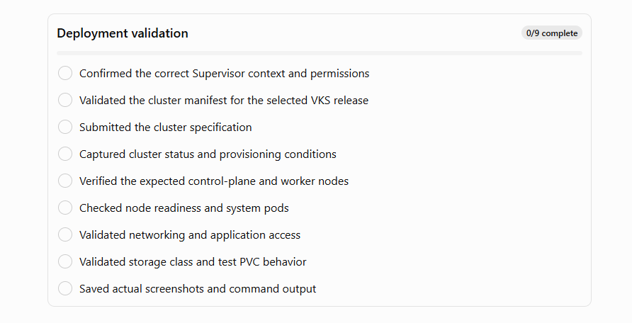
Expected outcome: A documented deployment attempt with evidence showing whether the cluster reached readiness and whether networking, storage, and application access behaved as expected. The checklist tracks your review; it does not automatically inspect or validate the environment.
7. Troubleshooting and Validation
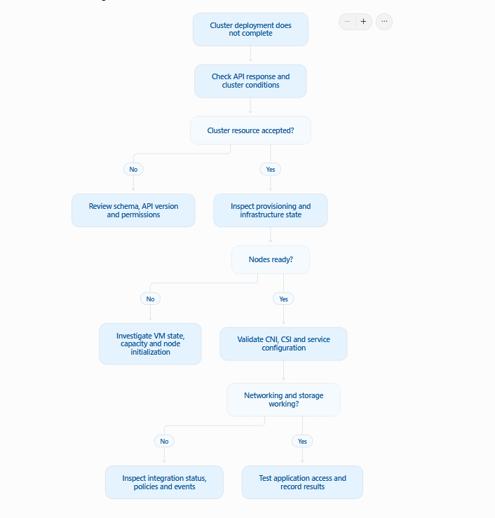
A VKS deployment can encounter problems at different layers. A structured troubleshooting process helps identify whether the issue originates in the API request, platform configuration, virtual infrastructure, Kubernetes initialization, networking, or storage.
Common Deployment Issues
| Symptom | Possible area to investigate | Initial diagnostic action |
|---|---|---|
| Cluster resource is rejected | API version, manifest schema, permissions | Review the API error and validate the manifest |
| Cluster remains pending | Resource provisioning, capacity, platform conditions | kubectl describe cluster production-vks01 -n app-platform |
| Expected nodes are missing | VM provisioning, cluster topology, controller conditions | Inspect cluster conditions and accessible VM resources |
Nodes remain NotReady | Node initialization, network connectivity, kubelet health | kubectl describe node <node-name> |
| System pods fail to start | CNI, image access, initialization, node resources | kubectl get pods -A |
| PVC remains pending | Storage class, CSI integration, storage policy, capacity | kubectl describe pvc <pvc-name> |
| Application is unreachable | Service configuration, DNS, routing, firewall, load balancing | Inspect the service and test connectivity along the expected access path |
These commands provide initial diagnostic information. Depending on the symptom, you may also need platform events, controller logs, infrastructure monitoring, or the relevant vCenter and network configuration.
Troubleshooting Workflow
Before Considering the Deployment Complete
Confirm that the following conditions have been checked:
- The cluster has reached its expected ready state.
- The control plane and expected worker nodes are healthy.
- Required networking components are operational.
- The intended storage classes are available.
- A test PVC can be provisioned where applicable.
- The load-balancing and application access paths work as designed.
- No unresolved errors prevent the intended workloads from running.
A cluster may be technically provisioned but still require additional configuration before it is suitable for production. Record any remaining limitations rather than treating initial cluster creation as proof of production readiness.
8. Key Takeaways
Deploying VKS on VMware Cloud Foundation 9.1 is a process that begins with infrastructure planning and ends with verified cluster and workload behavior.
The key lessons from this implementation workflow are:
- Infrastructure readiness comes first. DNS, NTP, compute, storage, routing, and IP allocation must support the intended cluster.
- The Supervisor and namespace establish the platform context. Resource availability, access permissions, and supported services determine what consumers can provision.
- Pre-deployment design decisions affect the result. VM classes, Kubernetes releases, networking, storage, registry access, and availability topology must be reviewed before deployment.
- Declarative provisioning is not the same as completed deployment. An accepted manifest must still pass provisioning, initialization, and readiness checks.
- The manifest must match the installed release. Placeholder values and examples from another VKS version should never be assumed to work unchanged.
- Cluster size should reflect workload requirements. Smaller/disposable clusters and larger/shared clusters have different operational characteristics.
- Validation must cover the complete stack. Control-plane health, worker readiness, CNI, storage, load balancing, and application access all matter.
- Lab evidence should come from actual results. Screenshots, command output, and troubleshooting observations should accurately reflect the environment in which the deployment was performed.
The overall objective is to establish a repeatable deployment process that can be reviewed, validated, and improved as the platform evolves.
9. What I Learned
This section should capture your own practical experience and explain what the deployment process revealed beyond the product documentation.
Use the following as a draft and personalize it after performing the lab.
Deploying a VKS cluster requires more preparation than simply defining the number of control-plane and worker nodes. The underlying infrastructure, namespace configuration, supported release, and available VM and storage classes all influence whether the requested cluster can be provisioned successfully.
One important lesson is that deployment readiness must be evaluated in stages. A valid cluster specification is only the first milestone. The platform must provision the required infrastructure, the Kubernetes nodes must initialize, and the networking and storage integrations must work before the environment can support its intended workloads.
Another lesson is that cluster sizing and isolation are architectural decisions rather than purely technical defaults. Smaller clusters can support team isolation and short-lived environments, while shared clusters require careful planning for capacity, permissions, resource contention, and operational ownership.
Finally, validation should be part of the deployment procedure from the beginning. Recording cluster conditions, node readiness, storage behavior, and application access makes the result easier to troubleshoot and gives future deployments a repeatable baseline.
Before publishing: Add two or three observations from your actual VKS lab. For example, describe which prerequisite required the most preparation, what the cluster status showed during provisioning, or how you verified storage and application connectivity. Do not describe the example deployment as successful unless you have completed and validated it.